
Hello there.
For something completely different now.
I have read about SRV6 and the benefits it brings. Never used it in production though.
Thus I decided give it a try, created a lab and configured it to use SRV6.
So let’s go.
Motivation
SRV6 (Segment Routing over IPV6) allows you to use the native IPv6 data plane to carry instructions (segments) for packet forwarding, essentially encoding network paths and functions directly in the packet header.
It is fairly efficient, you use segments as part of network functions, utilizes extensions already built in the IPv6 headers, allows for source routing and because the transit routers just forward IPV6 packets, it simplifies the setup of your core network.
Due to this you do not need for example MPLS labels and it supports L3VPNs, L2VPNs and other technologies, thus it has “Extensibility”.
SETUP
Figure 1. shows the network setup we will use.
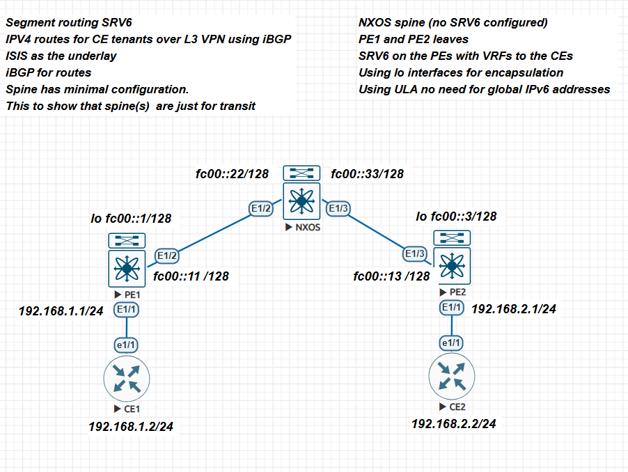
A few remarks.
- CE1 and CE2 are the customer equipment devices. We just use IPv4 and a default route to connect to the core. Of course we could have also configured eBGP for this. I wanted to keep it simple.
- The core consists of Nexus 9000v switches running version 9.3(5)
- Enable srv6 and IS-IS.
- On the 9000v you need to actually assign an IPv6 address for IPv6 to function.
- NXOS is a transit router. We are also using ULA IPv6 addresses for the data plane. Of course you could use global addresses but remember global addresses are routable on the Internet. Thus in a production environment you need to have your firewall prevent access (you use an IPv6 firewall in your network don’t you!).
- We implement IS-IS as the underlay.
- We configure a VRF at the PE edges to communicate with the CE devices.
- Notice, the clients are not running IPv6 just IPv4. Our data plane is IPv6 only but we are routing IPv4 on top of it.
Configurations
CE1 and CE2
ce1#sh ip int bri
Interface IP-Address OK? Method Status Protocol
FastEthernet0/0 unassigned YES unset administratively down down
Ethernet1/0 unassigned YES unset up up
Ethernet1/1 192.168.1.2 YES manual up up
Ethernet1/2 unassigned YES unset up up
Ethernet1/3 unassigned YES manual up up

ip route 0.0.0.0 0.0.0.0 192.168.1.1

ce2#sh ip int bri
Interface IP-Address OK? Method Status Protocol
FastEthernet0/0 unassigned YES unset administratively down down
Ethernet1/0 unassigned YES unset up up
Ethernet1/1 192.168.2.2 YES manual up up
Ethernet1/2 unassigned YES unset up up
Ethernet1/3 unassigned YES unset up

ip route 0.0.0.0 0.0.0.0 192.168.2.1
NXOS
First the IS-IS router instance.
router isis 1
 net 49.0001.0000.0000.0002.00
 is-type level-2
 metric-style transition
 address-family ipv6 unicast
 segment-routing srv6
 locator mylocator

interface Ethernet1/2
 ipv6 router isis 1

interface Ethernet1/3
 ipv6 router isis 1
Notice that I have defined the locator for SRV6 but I do not have such locator configured on this device. It is not needed.
The interfaces.
nxos-9k# sh ipv6 int bri
IPv6 Interface Status for VRF "default"(1)
Interface IPv6 Address/Link-local Address Interface Status
                                          prot/link/admin
Eth1/2    fc00::22                        up/up/up
          fe80::200:ff:fe00:2002
Eth1/3    fc00::33                        up/up/up
          fe80::200:ff:fe00:3003
interface Ethernet1/2
 no switchport
 mac-address 0000.0000.2002
 ipv6 address fc00::22/128
 ipv6 router isis 1
 no shutdown

interface Ethernet1/3
 no switchport
 mac-address 0000.0000.3003
 ipv6 address fc00::33/128
 ipv6 router isis 1
 no shutdown
One more thing, notice that I am giving each interface a custom MAC address. In my lab (EVE-NG) the interfaces are created with the same mac addresses, this cause issues thus the new assignment of mac addresses.
PE1 and PE2
Below are relevant parts for each device configuration.
PE1
segment-routing
 srv6
 locators
 locator mylocator
 prefix fc00:0:0:1::/64
 encapsulation
 source-address fc00::1

route-map EVERYTHING permit 10
vrf context management
vrf context one
 rd 1:1
 address-family ipv4 unicast
 route-target import 1:1
 route-target export 1:1
-----
interface Ethernet1/1
 no switchport
 mac-address 0000.0000.aaaa
 vrf member one
 ip address 192.168.1.1/24
 no shutdown

interface Ethernet1/2
 no switchport
 mac-address 0000.0000.1001
 ipv6 address fc00::11/128
 ipv6 router isis 1
 no shutdown
-----
router isis 1
 net 49.0001.0000.0000.0001.00
 metric-style transition
 address-family ipv6 unicast
 segment-routing srv6
 locator mylocator
router bgp 64512
 router-id 10.0.0.1
 segment-routing srv6
 locator mylocator
 alloc mode per-vrf
 address-family ipv4 unicast
 redistribute direct route-map EVERYTHING
 address-family vpnv4 unicast
 neighbor fc00::3
 remote-as 64512
 update-source loopback0
 address-family ipv4 unicast
 address-family vpnv4 unicast
 send-community
 send-community extended
 vrf one
 address-family ipv4 unicast
 redistribute direct route-map EVERYTHING
 segment-routing srv6
 alloc mode per-vrf
 address-family ipv6 unicast
 redistribute direct route-map EVERYTHING
PE2
segment-routing
 srv6
 locators
 locator mylocator
 prefix fc00:0:0:3::/64
 encapsulation
 source-address fc00::3

route-map EVERYTHING permit 10
vrf context management
vrf context one
 rd 1:1
 address-family ipv4 unicast
 route-target import 1:1
 route-target export 1:1

interface Ethernet1/1
 no switchport
 mac-address 0000.0000.bbbb
 vrf member one
 ip address 192.168.2.1/24
 no shutdown

interface Ethernet1/3
 no switchport
 mac-address 0000.0000.1002
 ipv6 address fc00::13/128
 ipv6 router isis 1
 no shutdown

interface loopback0
 ipv6 address fc00::3/128
 ipv6 router isis 1

router isis 1
 net 49.0001.0000.0000.0003.00
 metric-style transition
 address-family ipv6 unicast
 segment-routing srv6
 locator mylocator
router bgp 64512
 router-id 10.0.0.3
 segment-routing srv6
 locator mylocator
 address-family ipv4 unicast
 redistribute direct route-map EVERYTHING
 address-family vpnv4 unicast
 neighbor fc00::1
 remote-as 64512
 update-source loopback0
 address-family ipv4 unicast
 address-family vpnv4 unicast
 send-community
 send-community extended
 vrf one
 address-family ipv4 unicast
 redistribute direct route-map EVERYTHING
 segment-routing srv6
 alloc mode per-vrf
 address-family ipv6 unicast
 redistribute direct route-map EVERYTHING
Of course the values I did use for AS, ULA and IS-IS routing will need to change for your particular case.
Notice the definition of the locator (on a 9000v you can only have one locator).
We use encapsulation, the loopback interface. We also define the VRF we will use to the CE devices.
Finally we use a route map to redistribute connected routes. the 9000v does not have a “redistribute connected” command anymore why I do not know.
Verification and Testing
If everything goes well you should be able to complete some verification steps and tests.
First you should be able to ping between PE1 and the spine.
pe1# ping6 fc00::22 source-interface ethernet 1/2
PING6 fc00::22 (fc00::22): 56 data bytes
64 bytes from fc00::22: icmp_seq=0 time=7.433 ms
64 bytes from fc00::22: icmp_seq=1 time=4.94 ms
64 bytes from fc00::22: icmp_seq=2 time=5.453 ms
64 bytes from fc00::22: icmp_seq=3 time=7.608 ms
64 bytes from fc00::22: icmp_seq=4 time=4.382 ms
Pings to the spine from the PEs should work. If not you need to fix IPv6.
Then check that IS-IS has formed adjacencies, if not fix the issue, SRV6 will not work.
 pe1# sh isis 1 topology
IS-IS process: 1
VRF: default
Topology ID: 0

IS-IS Level-1 IS routing table

IS-IS Level-2 IS routing table
nxos-9k.00, Instance 0x00000014
 *via nxos-9k, Ethernet1/2, metric 40
nxos-9k.02, Instance 0x00000014
 *via nxos-9k, Ethernet1/2, metric 80
pe2.00, Instance 0x00000014
 *via nxos-9k, Ethernet1/2, metric 80
You should see something similar on the other 9000v switches.
pe1# sh ipv6 route isis-1
IPv6 Routing Table for VRF "default"
'*' denotes best ucast next-hop
'**' denotes best mcast next-hop
'[x/y]' denotes [preference/metric]

fc00::3/128, ubest/mbest: 1/0
 *via fe80::200:ff:fe00:2002, Eth1/2, [115/81], 19:42:53, isis-1, L2
fc00::13/128, ubest/mbest: 1/0
 *via fe80::200:ff:fe00:2002, Eth1/2, [115/120], 19:42:53, isis-1, L2
fc00::22/128, ubest/mbest: 1/0
 *via fe80::200:ff:fe00:2002, Eth1/2, [115/80], 19:42:54, isis-1, L2
fc00::33/128, ubest/mbest: 1/0
 *via fe80::200:ff:fe00:2002, Eth1/2, [115/80], 19:42:54, isis-1, L2
fc00:0:0:3::/64, ubest/mbest: 1/0
 *via fe80::200:ff:fe00:2002, Eth1/2, [115/80], 16:05:06, isis-1, L2
On PE2 you should see something similar. Finally show the locator information.
pe1# show srv6 locator detail
Name ID Prefix Status
-------------------- ------- ------------------------ ------------
mylocator 1 fc00:0:0:1::/64 Up
Number of SID: 4
Create time: 01-14 00:07:48.960784
Modify time: 01-14 03:17:45.982995, reason: Locator up
It should be up. I forgot the encapsulation command and could not understand why things were not working!
Now BGP should be working.
pe1# sh bgp all summary
BGP summary information for VRF default, address family IPv4 Unicast
BGP router identifier 10.0.0.1, local AS number 64512
BGP table version is 3, IPv4 Unicast config peers 1, capable peers 1
0 network entries and 0 paths using 0 bytes of memory
BGP attribute entries [0/0], BGP AS path entries [0/0]
BGP community entries [0/0], BGP clusterlist entries [0/0]

Neighbor V AS MsgRcvd MsgSent TblVer InQ OutQ Up/Down State/PfxRcd
fc00::3 4 64512 1189 1186 3 0 0 19:31:06 0

BGP summary information for VRF default, address family IPv6 Unicast

BGP summary information for VRF default, address family VPNv4 Unicast
BGP router identifier 10.0.0.1, local AS number 64512
BGP table version is 9, VPNv4 Unicast config peers 1, capable peers 1
2 network entries and 2 paths using 488 bytes of memory
BGP attribute entries [1/172], BGP AS path entries [0/0]
BGP community entries [0/0], BGP clusterlist entries [0/0]

Neighbor V AS MsgRcvd MsgSent TblVer InQ OutQ Up/Down State/PfxRcd
fc00::3 4 64512 1189 1186 9 0 0 19:31:06 1

BGP summary information for VRF default, address family VPNv6 Unicast
You see two entries because you have vpnv4 and ipv4 unicast entries.
Now for the pay-off:
pe1# sh ip route vrf one
IP Route Table for VRF "one"
'*' denotes best ucast next-hop
'**' denotes best mcast next-hop
'[x/y]' denotes [preference/metric]
'%<string>' in via output denotes VRF <string>

192.168.1.0/24, ubest/mbest: 1/0, attached
 *via 192.168.1.1, Eth1/1, [0/0], 20:05:28, direct
192.168.1.1/32, ubest/mbest: 1/0, attached
 *via 192.168.1.1, Eth1/1, [0/0], 20:05:28, local
192.168.2.0/24, ubest/mbest: 1/0
 *via fe80::200:ff:fe00:2002%default, Eth1/2, [200/0], 16:14:39, bgp-64512, internal, tag 64512
As you can see we see the network from CE2 received via Eth1/2. You will see the same on PE2 and the CE1 IPv4 network will be visible.
Finally from either CE we should be able to ping the other side.
ce2#ping 192.168.1.2
Type escape sequence to abort.
Sending 5, 100-byte ICMP Echos to 192.168.1.2, timeout is 2 seconds:
!!!!!

ce1#ping 192.168.2.2
Type escape sequence to abort.
Sending 5, 100-byte ICMP Echos to 192.168.2.2, timeout is 2 seconds:
!!!!!
Bingo! We are done.
Final Remarks
Of course this is a very simple setup. While you could load the complete configurations at once, I would recommend the steady approach.
Configure IPv6, then IS-IS, go onto the locator and VRFs and finally BGP. To me at least it gave me a workflow on how to configure it from scratch.
- In a data center or production environment you will need more spines routers (redundancy).
- You will also have several PEs and CEs. You will then use eBGP to exchange routes between them.
- You can use OSPF or BGP for the underlay. I did use IS-IS because it is very simple to implement.
- In a data center environment a Route Reflector or reflectors should also be used. Cisco recommends this since it will allow scalability as your PEs will peer with the reflector(s).
You can use GUAs addresses as stated. However, ULAs gives you flexibility, do not need to waste addresses (although with the vast amount of IPv6 addresses that is not a problem).
Using SRV6 eliminates the use of MPLS labels, LDP or RSVP-TE. This simplifies your control plane and because the scalability of the IPv6 address space it gives you native support for advanced capabilities like network slicing, traffic engineering, end-to-end encryption and more.
There you have it.
Hope you enjoy this lab.
Ciao.