
Hello there,
I thought I was done with PVE, then I noticed that some users had issues with VLANs, trunks, etc.
In principle it should be fairly straight forward to configure VLANs (not VXLANs) however, using the native Linux way could be a bit complicated sometimes.
OvS on the other hand was created with virtualization in mind and SDN in particular. A key point is that it supports Open Flow and allows for separation of the data plane and control plane.
Understanding and implementing it is easier said that done, so keep on reading.
Rationale
PVE will allow you to create VMs and containers, it will also allow you to access them. It will also allow communications between them using its security tools.
However, there will be times when you may need access to external devices and would like to separate access to those devices also.
You can, of course, use SDN in smaller networks, though VLANs are as good as well. PVE, being Linux-based has two ways of achieving this: traditional bridging or using Open VSwitch.
Both methods are not difficult to do; of course, if you are trying a complicated setup, you go down a rabbit hole very quickly.
We will create a couple of VLANs using OvS, then we will use a ToR (Top of the rack) switch, and we will trunk the VLANs we created to it. Finally, we achieved separation and security by connecting the ToR to a Cisco ASAv, which will allow the VMs access to the Internet. It will also allow access between VMs, if you add the corresponding rules on the firewall.
Setup
The following figure shows the network setup we are using.
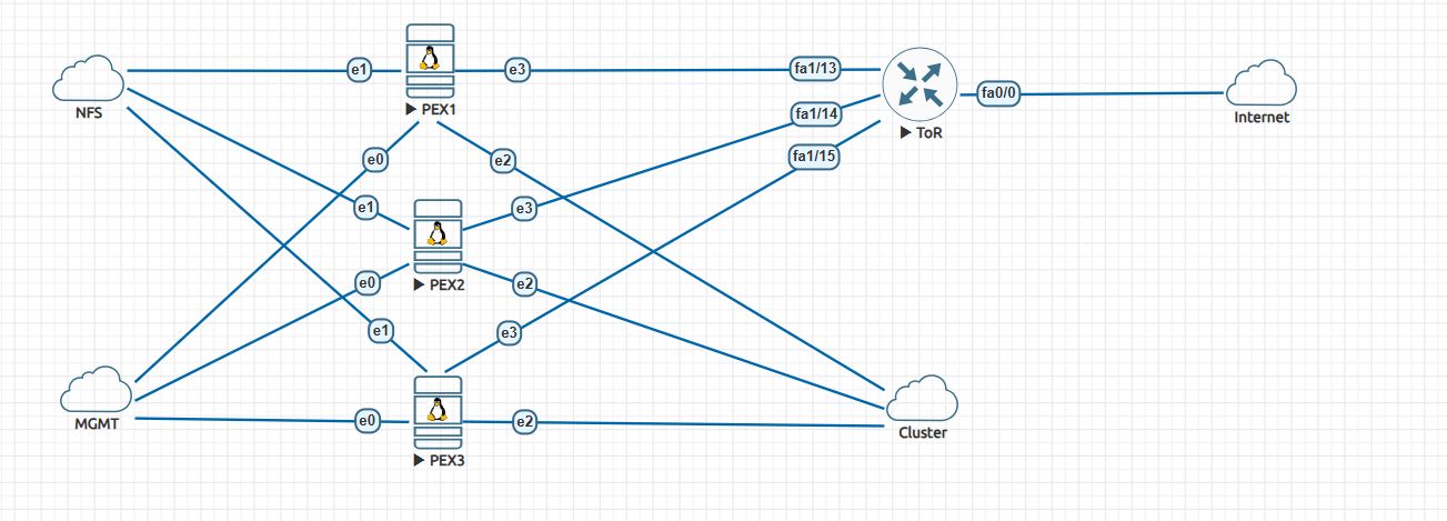
The setup consists of:
- An existing Linux bridge, created by default by PVE. We use it for management.
- Three OVS bridges. One for communication to the NFS backend, one for creating the cluster, and finally one for VLANs and for bridging the VLANs.
- A ToR switch that trunks to each PVE node.
- A Cisco ASAv that connects to the ToR switch.
Configurations
PVE
This is a standard PVE cluster using a dedicated network for management.
Before creating the cluster, add an OvS bridge. Choose the interface you will use for cluster communications. Create the bridge for NFS storage, and create the OvS bridge for connecting to the ToR device.
You should see the following in the file “/etc/inetwork/interfaces” on each node after the bridges are created.
# network interface settings; autogenerated
# Please do NOT modify this file directly, unless you know what
# you're doing.
#
# If you want to manage parts of the network configuration manually,
# please utilize the 'source' or 'source-directory' directives to do
# so.
# PVE will preserve these directives, but will NOT read its network
# configuration from sourced files, so do not attempt to move any of
# the PVE managed interfaces into external files!

auto lo
iface lo inet loopback

iface ens3 inet manual

auto ens4
iface ens4 inet manual
 ovs_type OVSPort
 ovs_bridge vmbr1

auto ens5
iface ens5 inet manual
 ovs_type OVSPort
 ovs_bridge vmbr2

auto ens6
iface ens6 inet manual
 ovs_type OVSPort
 ovs_bridge vmbr3

auto vmbr0
iface vmbr0 inet static
 address 10.229.128.233/24
 gateway 10.229.128.10
 bridge-ports ens3
 bridge-stp off
 bridge-fd 0

auto vmbr1
iface vmbr1 inet static
 address 192.168.1.133/24
 ovs_type OVSBridge
 ovs_ports ens4

auto vmbr2
iface vmbr2 inet static
 address 172.16.1.3/24
 ovs_type OVSBridge
 ovs_ports ens5

auto vmbr3
iface vmbr3 inet manual
 ovs_type OVSBridge
 ovs_ports ens6

source /etc/network/interfaces.d/*
Several things to notice:
- The ens3 (this will be different for your devices) is assigned to the Linux bridge.
- The other interfaces are declared as being part of OvS and assigned to the particular bridge.
- Bridge vmbr0 is used for management.
- Bridges vmbr1, vmbr2 are for NFS and cluster communications and thus get an IP address.
- Bridge vmbr3 is used for the trunk that will carry VLAN information between VMS and the ToR switch.
Ease as pie, isn’t it?
Now you can create the cluster and attach the NFS backend storage. You already know this drill (I hope you do).
VLANs
Now that you have the infrastructure working, let’s create a couple of VMs (or containers, whatever you wish).
I will not go through the process; it is straightforward, however, make sure:
- Choose the correct bridge; in our case, it is vmbr3
- Assign the VLAN tag (100, 200, etc).
- Choose a default gateway for this VM; it will be created on the ToR switch later.
- Uncheck the “firewall” box. We are not using PVE to control access.
- Create other VMS or VLANs.
Now start the VMs and open a console. You will not be able to get out of it, you should be able to ping other VMs in the same network.
Let’s take a look at what PVE did in the background in terms of networking. On the PVE node you created one the VMs, issue the command shown below.
root@pve-3:~# ip add
1: lo: <LOOPBACK,UP,LOWER_UP> mtu 65536 qdisc noqueue state UNKNOWN group default qlen 1000
 link/loopback 00:00:00:00:00:00 brd 00:00:00:00:00:00
 inet 127.0.0.1/8 scope host lo
 valid_lft forever preferred_lft forever
 inet6 ::1/128 scope host noprefixroute
 valid_lft forever preferred_lft forever
2: ens3: <BROADCAST,MULTICAST,UP,LOWER_UP> mtu 1500 qdisc fq_codel master vmbr0 state UP group default qlen 1000
 link/ether 00:50:01:00:03:00 brd ff:ff:ff:ff:ff:ff
 altname enp0s3
 altname enx005001000300
3: ens4: <BROADCAST,MULTICAST,UP,LOWER_UP> mtu 1500 qdisc fq_codel master ovs-system state UP group default qlen 1000
 link/ether 00:50:01:00:03:01 brd ff:ff:ff:ff:ff:ff
 altname enp0s4
 altname enx005001000301
 inet6 fe80::250:1ff:fe00:301/64 scope link proto kernel_ll
 valid_lft forever preferred_lft forever
4: ens5: <BROADCAST,MULTICAST,UP,LOWER_UP> mtu 1500 qdisc fq_codel master ovs-system state UP group default qlen 1000
 link/ether 00:50:01:00:03:02 brd ff:ff:ff:ff:ff:ff
 altname enp0s5
 altname enx005001000302
 inet6 fe80::250:1ff:fe00:302/64 scope link proto kernel_ll
 valid_lft forever preferred_lft forever
5: ens6: <BROADCAST,MULTICAST,UP,LOWER_UP> mtu 1500 qdisc fq_codel master ovs-system state UP group default qlen 1000
 link/ether 00:50:01:00:03:03 brd ff:ff:ff:ff:ff:ff
 altname enp0s6
 altname enx005001000303
 inet6 fe80::250:1ff:fe00:303/64 scope link proto kernel_ll
 valid_lft forever preferred_lft forever
6: ovs-system: <BROADCAST,MULTICAST> mtu 1500 qdisc noop state DOWN group default qlen 1000
 link/ether f6:b3:2a:11:db:ea brd ff:ff:ff:ff:ff:ff
7: vmbr1: <BROADCAST,MULTICAST,UP,LOWER_UP> mtu 1500 qdisc noqueue state UNKNOWN group default qlen 1000
 link/ether 00:50:01:00:03:01 brd ff:ff:ff:ff:ff:ff
 inet 192.168.1.133/24 scope global vmbr1
 valid_lft forever preferred_lft forever
 inet6 fe80::f476:33ff:fe60:ae46/64 scope link proto kernel_ll
 valid_lft forever preferred_lft forever
8: vmbr2: <BROADCAST,MULTICAST,UP,LOWER_UP> mtu 1500 qdisc noqueue state UNKNOWN group default qlen 1000
 link/ether 00:50:01:00:03:02 brd ff:ff:ff:ff:ff:ff
 inet 172.16.1.3/24 scope global vmbr2
 valid_lft forever preferred_lft forever
 inet6 fe80::e0d7:c8ff:fe53:8540/64 scope link proto kernel_ll
 valid_lft forever preferred_lft forever
9: vmbr3: <BROADCAST,MULTICAST,UP,LOWER_UP> mtu 1500 qdisc noqueue state UNKNOWN group default qlen 1000
 link/ether 00:50:01:00:03:03 brd ff:ff:ff:ff:ff:ff
 inet6 fe80::84fb:22ff:fe5d:1a45/64 scope link proto kernel_ll
 valid_lft forever preferred_lft forever
10: vmbr0: <BROADCAST,MULTICAST,UP,LOWER_UP> mtu 1500 qdisc noqueue state UP group default qlen 1000
 link/ether 00:50:01:00:03:00 brd ff:ff:ff:ff:ff:ff
 inet 10.229.128.233/24 scope global vmbr0
 valid_lft forever preferred_lft forever
 inet6 fe80::250:1ff:fe00:300/64 scope link proto kernel_ll
 valid_lft forever preferred_lft forever
21: veth100i0@if2: <BROADCAST,MULTICAST,UP,LOWER_UP> mtu 1500 qdisc noqueue master ovs-system state UP group default qlen 1000
 link/ether fe:0e:b3:c7:03:f4 brd ff:ff:ff:ff:ff:ff link-netnsid 0
The interesting bit is at the bottom.
An interface “vethXXXi0@ifx”, is created, in our case “veth100i0@if2”.
100 is the VLAN we are using, and veth is a virtual interface that allows, in this case, containers to communicate with each other. They are normally created in pairs. I will not go too much deeper on it, you can Google it.
The fun part starts now. We would like to connect to another device on that VLAN but outside of the cluster.
Of course, you do not need a Cisco switch or Cisco ASA; any managed switch that understands trunks will do. And any firewall (like OPNsense or PFsense) will also do.
Managed switch and firewall.
ToR
Connect each PVE to the ToR switch as per the network diagram.
This is the configuration of the switch:
hostname tor
!
boot-start-marker
boot-end-marker
!
!
no aaa new-model
memory-size iomem 5
ip cef
!
no ip domain lookup
!
multilink bundle-name authenticated
!
!
archive
 log config
 hidekeys
!
!
interface FastEthernet0/0
 no ip address
 ip virtual-reassembly
 duplex auto
 speed auto
!
interface FastEthernet0/1
 no ip address
 shutdown
 duplex auto
 speed auto
!
interface FastEthernet1/0
!
interface FastEthernet1/1
!
interface FastEthernet1/2
!
interface FastEthernet1/3
!
interface FastEthernet1/4
!
interface FastEthernet1/5
!
interface FastEthernet1/6
!
interface FastEthernet1/7
!
interface FastEthernet1/8
!
interface FastEthernet1/9
!
interface FastEthernet1/10
!
interface FastEthernet1/11
!
interface FastEthernet1/12
 description trunk to ASA
 switchport mode trunk
!
interface FastEthernet1/13
 description trunk to pve1
 switchport mode trunk
!
interface FastEthernet1/14
 description trunk to pve2
 switchport mode trunk
!
interface FastEthernet1/15
 description trunk to pve3
 switchport mode trunk
!
interface Vlan1
 no ip address
!
interface Vlan100
 ip address 10.10.100.254 255.255.255.0
 ip virtual-reassembly
 ip ospf 10 area 0
!
interface Vlan200
 ip address 10.10.200.254 255.255.255.0
 ip virtual-reassembly
 ip ospf 20 area 0
!
router ospf 10
 router-id 10.10.100.254
 log-adjacency-changes
 network 10.10.100.0 0.0.0.255 area 0
!
router ospf 20
 router-id 10.10.200.254
 log-adjacency-changes
 network 10.10.200.0 0.0.0.255 area 0
!
ip forward-protocol nd
!
!
ip http server
no ip http secure-server
!
!
control-plane
!
!
!
line con 0
 exec-timeout 0 0
line aux 0
line vty 0 4
 exec-timeout 0 0
 login
!
!
end
For this kind of switch, you also need to use the “vlan database” to create the VLANs.
It is a fairly standard setup. Ports fastE 1/13, 1/14, and 1/15 are configured as trunks. Port fastE 1/12 is the same, but it is connected directly to Gig0/0 on the ASA. Do not be confused with the “IP virtual re-assembly” and OSPF setup.
I was testing NAT, and then I decided to pair the switch with the ASA running OSPF. You do not need them.
You will notice that I created a couple of SVI interfaces, VLAN 100 and VLAN 200.
They got IP addresses (but not the gateway addresses, which will be configured at the ASA). In this fashion, I can test that I can ping the VMs on the PVE cluster.
If everything is set up correctly, you should be able to ping from the VMs to the VLANs configured on the switch.
Congratulations, you have trunking configured and can access devices outside PVE. You could, in principle, now have devices outside the cluster. For example, cameras that need to talk to a server on the cluster.
ASA
Configuring the ASA is not that difficult., I will not go over how to set up rules or configure NAT. It will depend on your device. The relevant bits are below:
interface GigabitEthernet0/0
 no nameif
 no security-level
 no ip address
!
interface GigabitEthernet0/0.100
 vlan 100
 nameif lan100
 security-level 100
 ip address 10.10.100.1 255.255.255.0
 ipv6 address fc00:1::1/64
 ipv6 enable
!
interface GigabitEthernet0/0.200
 vlan 200
 nameif lan200
 security-level 100
 ip address 10.10.200.1 255.255.255.0
 ipv6 address fc00:1:0:1::1/64
 ipv6 enable
!
interface GigabitEthernet0/1
 nameif outside
 security-level 0
 ip address dhcp setroute
 ipv6 address autoconfig
 ipv6 enable
 ipv6 nd suppress-ra
We configure each interface with the gateway IPs we set up the VLANs earlier. Notice that on an ASA, you configure sub-interfaces, and the ASA takes care of negotiating the trunking with the switch.
You do not need the IPv6 stuff. I decided to add IPv6 so the VMs would get it. Perhaps a topic for another blog.
If the firewall can access the Internet and you configured NAT, VMs will be able to access it.
In addition, you can now control what the VMs in the cluster can access.
Conclusions
There you have it. Creating VLANs using OvS is not that complicated, at least for the simple setup we just showed.
Hope you enjoyed the blog.
Happy networking.
Ciao.